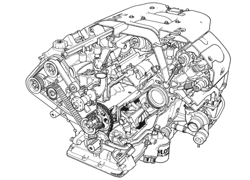
8 Cylinder Engine (918)
Introduced in the spring of 1996, the Lotus type 918 3.5 liter V8 engine incorporates the following features:
Cylinder Block
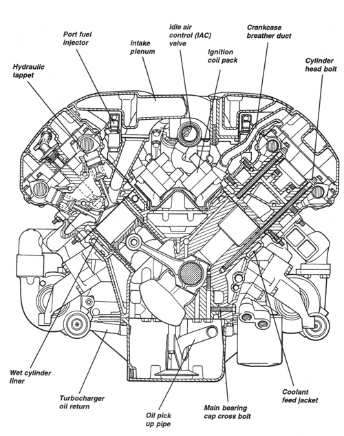
The aluminum alloy (LM25TF) cylinder block comprises two 'open deck'
type cylinder banks angled at 90° to each other and mounted on a common
crankcase. The RH bank is staggered ahead of the LH bank and contains
cylinders 1,2,3,4 with cylinders 5,6,7,8 designated as the LH bank, counting
from the front in both cases. Cast iron, push fit 'wet', cylinder liners are
spigotted into the block, seated on a flange near the bottom of the swept
volume, and clamped down by the cylinder head. The crankcase extends some
way below the crankshaft centerline, and is further stiffened by cross
bolted spheroidal graphite cast iron main bearing caps and a cast alloy
sump.
Cylinder Head
Each of the two aluminium alloy (LM25TF) cylinder heads contain four
valves for each cylinder in 'pent roof' combustion chambers, with the inlet
and exhaust valves angled at 42° to each other, and at 21.5° and 20.5°
respectively to the cylinder axis. A twin electrode 14mm spark plug is
centrally placed in each chamber and accessed via a deep tunnel in the head
casting. Each cylinder head is retained by 10 long M11 setscrews threaded
deep into the base of the block. The top face of each head coincides with
the centerline of the two overhead camshafts whose five bearings run
directly in the head with individual bearing caps.
Crankshaft and Reciprocating Components
The forged steel, four throw, single plane crankshaft uses five main
bearings with each bearing cap secured by four vertical bolts, and two cross
bolts through the sides of the crankcase skirt. End float is controlled by
thrust washers either side of no.4 main bearing. A torsional vibration
damper is incorporated with the auxiliary drive pulley and mounted on the
front end of the crankshaft, and a steel flywheel fixed by eight bolts to
the rear. Each crankpin is shared by a connecting rod big end from each
cylinder bank. The forged steel 'I' section connecting rods use straight
split big end caps, retained by two bolts, fully floating little ends and
gudgeon pins retained in the pistons by wire circlips. The cast alloy
pistons have bowl shaped crowns and use a barrel faced compression ring, a
'Napier' type scaper second ring, and an oil control ring pack consisting of
two scraper rails and a separator. Bore and stroke dimensions of 83 x 81 mm
provide a swept volume of 3506cc.
Camshaft Drive and Valvegear
Drive to the twin overhead camshafts of each cylinder head is provided
by a two stage driveline at the front of the engine. A short primary stage
comprises a Morse inverted tooth chain drive from the crankshaft to an
intermediate shaft contained within the engine front cover. This stage
accommodates the 2:1 reduction and enables a common size of toothed pulley
to be used throughout the secondary stage, also benefiting power unit width.
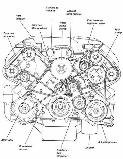
The secondary stage uses a pair of pulleys on the intermediate shaft to
drive separate synthetic toothed belts for each cylinder bank, each belt
controlled by a temperature compensating 'dynamic' tensioner on the
non-drive side, with a steady wheel on the drive side to inhibit
oscillation.
Each of the four camshafts is supported in five bearings and operates eight inlet or exhaust valves via maintenance free, inverted bucket, hydraulic tappets. The 33.5mm inlet and 30.0mm exhaust valves have solid stems, operate in replaceable guides and seats, and are closed by single coil springs. Valve stem seals are used to control the flow of lubricant to the valve guides.
Turbocharging and Engine Management Systems
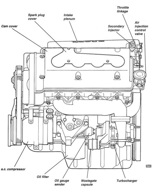
Twin non-handed Garrett T25 type turbochargers with integral wastegates
are used, one for each cylinder bank, to provide up to 0.75 bar (10.9 psi)
boost pressure. Each turbocharger is mounted alongside the outside rear of
each cylinder bank, on a cast iron (Niresist S5S) manifold, and supplies
charge air to the opposite cylinder bank. Charge air from each compressor is
discharged via a cast alloy duct, to a throttle body at the rear of the
engine. The throttle body contains two butterfly valves, one for each
cylinder bank, operated by the throttle cable via a rising rate linkage for
optimum control at small openings, and quick response at wider openings. Air
then flows into an intake plenum comprising a common chamber, two plenum
chambers, and eight inlet tracts. The small common chamber sited immediately
above the throttle body, allows air supplied from the two turbochargers to
mix and balance pressures before separating into two plenum chambers, one
mounted over each cylinder head's cam cover. From each plenum chamber, four
inlet tracts lead to a short injector housing (intake manifold) on the
opposite cylinder head.
Each branch of the two injector housings is fitted with a dual spray injector to serve its bifurcated inlet port, and is operated sequentially by the engine management ECU. A further two, 'secondary' injectors, are fitted into the rear of the plenum chamber and operate at constant frequency only under conditions of greatest
demand. Two twin coil ignition units are mounted within the 'V' and are controlled by the engine management ECU which receives engine speed and position signals from the crankshaft front pulley and rear end of the RH inlet camshaft.
In order to reduce nitrous oxide emissions, exhaust gas recirculation (EGR) is used, whereby exhaust gases collected from the LH exhaust manifold are piped to an EGR control valve mounted at the rear of the intake plenum. Air injection is used for a short period following a cold start in order to help complete combustion of the exhaust gas and to speed the warm up time of the catalytic converters. An electric air pump is used to supply air into drillings in the head emerging just downstream of the exhaust valve guides. The stepper motor for idle speed control is mounted on the underside of the intake plenum, and controls the amount of air allowed to by-pass the throttle butterflies. Other engine management sensors are located as follows: Manifold air pressure (MAP) sensor - top rear of intake plenum; intake air temperature (IAT) sensor - compressor RH duct; knock sensor - crankcase breather cover in 'V'. For further details of the engine management system, see Service Notes Section EMM.
Cooling System
A centrifugal water pump is mounted on the front of the block, driven by
multi-rib 'V' belt from the crankshaft. Water is pumped via passageways in
the front cover, into the outside of each cylinder bank and via a window in
each cylinder's water jacket, is circulated around each cylinder liner.
Coolant then flows up into the
head and around the combustion chamber before returning to a passage on the inside of the block and back to the pump. Take-offs for the heater are provided at the rear of each cylinder bank coolant return passage, with a heater return connection in the coolant return pipe at the LH front of the engine bay.
A by-pass type thermostat then controls the proportion of coolant which flows through external pipework to the radiator, or back to the pump impeller for re-circulation. Cooling take-offs for the turbochargers are provided at the front of the outer water gallery at each side of the block, and return from the turbochargers to the header tank.
Lubrication
The trochoidal oil pump, uses a 9 lobe rotor, splined to the nose of the
crankshaft, and an eccentrically constrained 10 lobe annulus housed within
the front cover. The pump draws oil stored in the baffled 'wet' sump through
a gauze strainer and suction pipe into the inlet side of the pump, and
outputs the pressurized oil into a drilling along the LH side of the
crankcase. An oil pressure relief valve is contained within the front cover,
and controls a passageway linking the pump outlet and inlet ports. Excessive
oil pressure is thus allowed to bleed off from the high to low pressure
side.
Pressurized oil then flows via a passageway along the LH side of the crankcase to the filter head which also provides takeoffs for the oil cooler and temperature/pressure gauge transducer. An upper port on the filter head connects with the crankcase passageway and directs oil via external pipework to the oil cooler radiator. The return pipe from the cooler connects to a lower port on the filter head which directs the flow into the outside of the canister type vertically mounted filter.
Filtered oil flows from the centre of the filter, through the filter head and into a second, lower, passageway along the LH side of the crankcase. Across drilling at the front of the block joins with the main gallery running along the centre of the 'V' which supplies, via vertical drillings, each of the five main bearings. The upper main bearing shells are grooved in order always to supply one end of a cross drilling in each crankshaft main journal, from which further drillings through the crankshaft provide an oil supply to each crankpin for lubrication of the big end bearings.
Feeding off the main oil gallery, four pairs of spray nozzles direct a jet of oil onto the underside of each piston crown in order to aid piston cooling.
Drillings at the inside centre of each cylinder bank provide an oil supply up to the deck face of each bank, where a connection is made with the adjacent cylinder head bolt hole. In the cylinder head, a transverse drilling is used to connect this bolt hole with two longitudinal oilways from which further drillings supply the camshaft bearings and hydraulic tappets. Oil return passageways are provided at the front and back of the cylinder head and block, through which oil is able to drain back into the sump.
Oil supply take-offs for the two turbochargers are provided at each rear end of the cylinder head oil galleries, with braided hoses used to link with the tops of the turbocharger bearing housings. Oil draining from each turbocharger is directed via an elbow pipe and connector hose to the sump.
Lubrication System Precautions
Auxiliary Drives
The water pump, alternator, a.c. compressor and power steering pump are
all driven by a single multi-rib 'V' belt from the front end of the
crankshaft, with a temperature compensating automatic tensioner mounted on
the front of the block.


