Michael O'Sullivan and his buddy Gary Gill did an excellent job of
documenting the process of installing a Blow Off Valve (BOV) on Gary's
Esprit S4s. They were even kind enough to provide all the images and files
in a format very close to what the Esprit Fact File already uses, thus
making it easier to include it here. Great job guys!
On a Difficulty Scale of 1 to 10, this procedure rates a 9.
Procedure
The following
step-by-step procedure is for installing the BOV on a 4-cylinder Esprit (including SE,
S4, S4s, GT3, and Sport300).
**Note: Click on any photo to see a larger image. Click the
Back button on your
browser to return to this page.
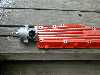
Parts
The following parts are needed for this installation procedure:
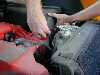
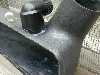
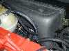
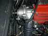
Drill 1.5" hole for pcv
fitting. Location is very important here. Our
fitting was under the airbox to look less conspicuous, but was a real pain to snake the
radiator hose from the BOV outlet back to our new
airbox intake fitting. An ideal spot would be on
the top side of the airbox, part of the way down
the neck that connects to the turbo intake hose
(i.e. where the left hand is in the picture
opposite). In this position the BOV outlet would
be only inches away from the BOV outlet and also
require less bending of the hose between the two.
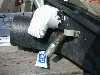
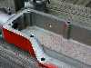
Attach PVC fitting and seal with
JB Weld
Allow it to dry (overnight). Paint
if desired
Replace airbox with filter and
attach/clamp new radiator hose.
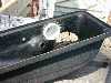
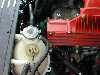
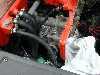
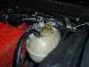
There simply wasn’t enough
room to keep the coolant tank in the same place
so it had to be moved. We remounted it to the
plenum clover with a simple metal bracket.
There are 4 hoses feeding into the
coolant tank of differing sizes. The 5/8"
line from the bottom needs to be lengthened, as
does the 3/8" line from the turbo. The other
two will actually be shortened when the tank is
remounted as they come from the front of the car
(routed via the right hand side trim panel, where
ECU is located).
Remove the tank and associated
hoses (be careful draining the tank full of
coolant), from the turbo (2/3’ long) and the
base of the tank (about 2-3" long), and the
other two top lines that run through the right
hand side trim panel. At this point I
recommend skipping to the BOV mounting as there
is plenty of room with the tank out of the way
(see section below).
The coolant level sensor wires
also need to be lengthened. A 2’ 3 core
cable was used to lengthen the line and it was
routed through the right hand side where the
original coolant tank hoses were fed.
Replace the turbo coolant line
with the 6’ replacement and route it through the right hand trim
panel for neatness.
Connect up the 2’ line
feeding the base of the tank.
Shorten the remaining two lines
appropriately and remount to the top of the tank.
Reconnect your extended sensor
wires to the coolant level sender unit atop the
tank.
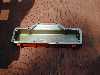
Fabricate a simple metal bracket,
4 holes drilled in a flat piece of metal and then
bent into a |__| shape. Ours was found at the
local Home Depot and can be seen in the picture
of the relocated tank.
Remove the plenum cover (8 bolts
13mm socket). Be very careful not to tear the
paper gasket when removing the plenum cover,
otherwise you’ll need a new one.
Remove boost line from the end of
plenum.
Attach T the boost line. New T
line will attach to BOV valve, while the other
line from the T boost line will be
remounted beneath the plenum.
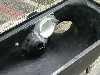
Drill 1" hole at the end of
the plenum to act as the intake source of the
BOV. Using a 1" hole saw. Drilling a small
pilot hole is recommended.
Drill 2 mounting holes and thread
for 3/8" x 1 ½" bolts (or which ever
size bolt/tap set you have available).
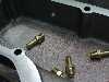
Drill a hole for a 3/8" NPT
tap hole beneath the plenum and thread for your
NPT boost line fitting to remount boost line. We
used brass 3/8" NPT tap fittings (from local
auto parts store) rather than re-using the ones
that were on the car. The reason for this is that
we could not get an appropriate metric tap with
the correct thread count for the original units.
We use 3/8" – 16 thread (16 threads per
inch) pattern as the only size we could find in
common. In fact the brass NPT fittings were
originally 24 threads per inch but we re-threaded
it using a die to 16 to match the hole already
threaded in the plenum cover.
Drill another hole for a 3/8"
NPT tap in the intake manifold. Have someone
press down on the accelerator pedal while you
insert a clean moist towel into the intake
manifold to catch fillings. Then, drill a pilot
hole first and go slowly using plenty of coolant
on the drill bit. Once tapped you can remove the
rag and also clean out other fillings in the
area. Screw in one of the brass NPT tap fittings
into the intake manifold. This is now your vacuum
source for the BOV.
Bolt BOV to plenum.
Replace plenum.
Attach the vacuum source line (the
line that is fitted to the intake manifold to the
left of the plenum) to the vacuum source of the
BOV and clamp either end.
Clamp the radiator hose from the
airbox to the BOV outlet.
Thanks to Lewis Gaskell who recommended the parts and explained the procedure to us. Gary Gill who provided a
beautiful S4s to drill holes into, in addition to doing
the work. Alan Elliot for tools and figuring out the best
way to remove/replace/re-route things.