| Background
The chargecooling system is comprised of several
components:
- Chargecooler (water/air intercooler)
- Pump
- Radiator
- Coolant header tank
- Interconnecting hoses
Esprit models with a chargecooler include 89.5MY to 93.5MY Esprit SE;
93MY to 95MY Esprit S4; 96MY to 96MY Esprit S4s; 96MY to 99MY Esprit GT3;
and 92MY to 95MY Sport300.
Starting with cars built in December 1993, a change was made to the
chargecooling system. Prior to this date, The chargecooling system was
fully independent from the engine cooling system. These cars can be
identified by the presence of two black metal coolant header tanks
side-by-side. The larger tank being for engine cooling and the smaller for
the Chargecooler. After the change date, the two systems were integrated
into one. These cars have one common frosted white plastic header tank
which supplies the coolant for both purposes.
In either version, the pump that circulates the coolant through the
system is identical and can be found in the same location: under the
intake plenum, attached to the auxiliary shaft housing. The auxiliary
shaft is engine-driven and is used to rotate the oil and chargecooler
pumps. It is located on the right front side of the engine block under the
intake plenum.
Accessing the chargecooler pump is one of the hardest parts of the
rebuild process due to its location. For this kind of job, it is essential
that you sit in the boot (trunk)
of the vehicle to perform your work. It is also necessary that you remove
certain components that are in the way including the air box, oil filter,
and iginition wires.
On a Difficulty Scale of 1 to 10, this procedure rates an 6.

Procedure
**Note: Click on any photo to see a larger image. Click the
Back button on your
browser to return to this page.
| 1 |
Loosen the two screws that hold the air box to the right side of the
engine bay. Disconnect the large diameter air hose connecting the air box
to the turbo as well as the smaller diameter hose at the bottom of the air
box for the fuel vapor recovery system. Set the air box and the air filter
aside. |
| 2 |
Disconnect the ignition wires from the ignition modules and move
them out of the way. Notice that the modules are numbered to match the
numbers on the wires. This makes it easier to match them up when
reconnecting them. |
| 3 |
Remove the oil filter. Make sure to put rags or paper towels
underneath to catch the oil that will drip out. This may be a good
time to do an oil change anyway. |
| 4 |
Disconnecting the hoses from the chargecooler pump while the pump is in
place may be difficult if the
clamps are facing the wrong way. The bottom hose connects the outlet
spigot
of the pump to the front (inlet) spigot on the side of the chargecooler.
To help in the pump removal, you can
disconnect this hose at the chargecooler end. |
| 5 |
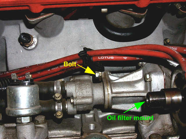
Remove the single 10mm bolt at the top of the pump (see arrow in the
picture below) using a ratchet with a small socket extension. Threaded on this bolt is also a clip to help route the ignition wires
neatly. Carefully remove this clip and set it aside. Now you can move
the ignition wires further out of the way. |
|
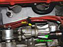 |
The chargecooler pump is located on the right side of
the engine, underneath the intake plenum. To gain access to it you
should remove the air box, air filter, oil filter and disconnect the ignition
wires. There is one 10mm screw
at the top that holds the pump in place. |
| 6 |
Gently wiggle the pump back until it clears the engine. It will be
a very tight fit because the pump has to move back about 5 inches and there
isn't a lot of room here due to all the hoses. Just be patient and work carefully. When the
pump clears the engine, rotate it right and pull it out a little to
give you more access to the inlet spigot hose clamp. |
| 7 |
Disconnect the hose clamp and wiggle the inlet (top) hose free. It
may be tightly held on there so it might take some persuasion. If so,
use a small flat blade screw driver to gently pry it off. |
| 8 |
The pump should now come out of the car with the outlet hose still
attached. You can now remove this hose if you wish. |
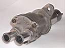 |
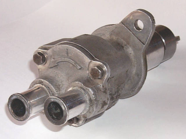
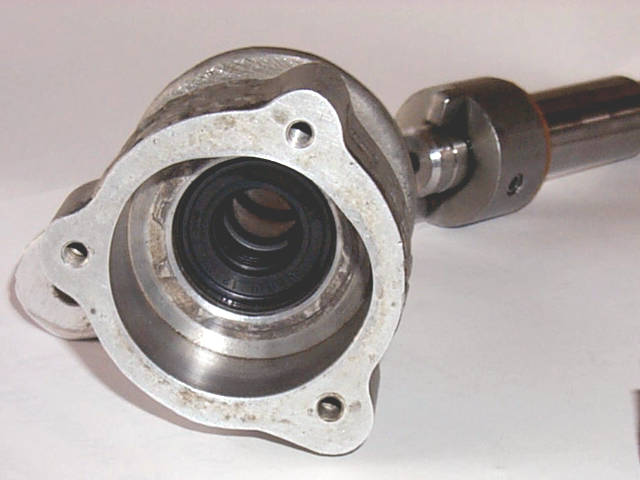
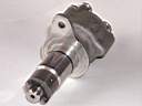
This is a rear view of the pump after it has been
removed from the engine. Note the two hose connections. The rightmost
one is the inlet spigot from the radiator. The leftmost one is the output
spigot to
the chargecooler.
|
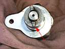
| 9 |
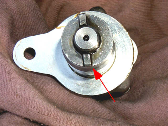
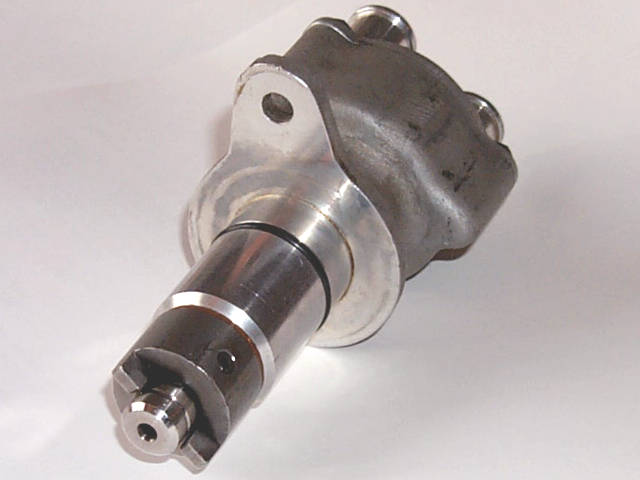
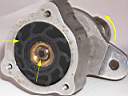
Note that the pump shaft has a tang on its tip (see arrow in picture
below) that is
slightly off center. Make sure that you memorize the position of this
tang in relation to the pump housing as soon as you remove the pump
from the car. This must be properly aligned with the auxiliary
shaft or the pump won't go back in. |
| The end of the pump shaft has a tang on its tip
that is
slightly off center. This tang couples with the end of the auxiliary
shaft and allows the pump to rotate. The tang and the auxiliary
shaft end must line up correctly or the pump cannot be fully
reinserted. |
|
| 10 |
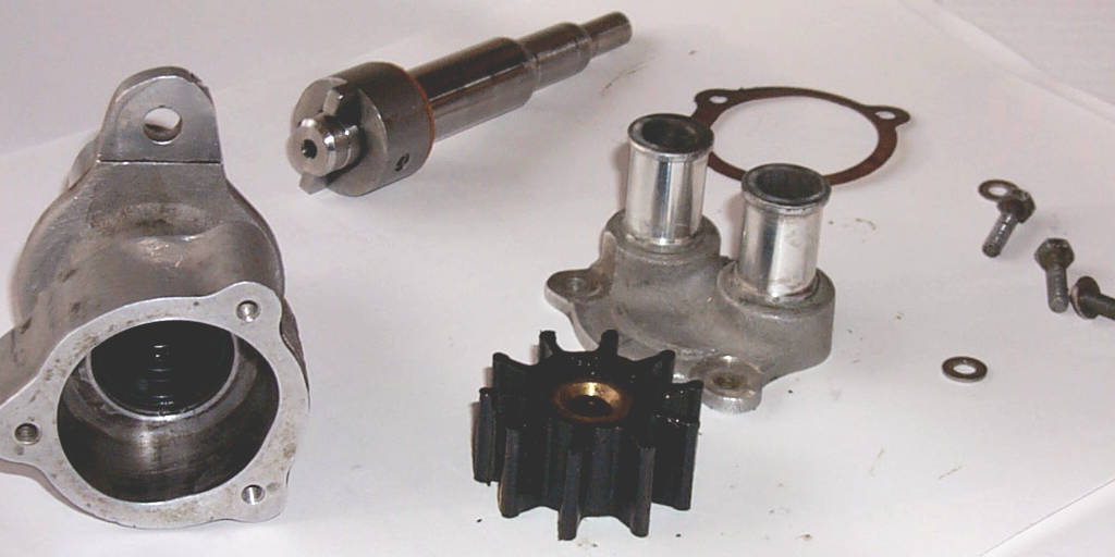
Disassemble the pump by removing the three 7mm screws that hold it
together. Scrape any gasket material from both mating surfaces and
make sure that they are clean and smooth so they will seal correctly
when you reassemble the pump. |
|
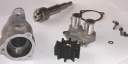 |
After removing the three screws that hold the pump
together, you can disassemble all the components. At the left is the
pump housing. The foreground shows the impeller. In the background you
can see the shaft and the paper gasket.
|
| 11 |
Remove the rubber impeller from the housing with some needle-nose
pliers. |
| 12 |
There are two rubber seals in the pump housing that prevent the oil
(shaft) side and coolant (impeller) side from leaking. It is recommended
that you replace these seals any time
you rebuild the pump. First, gently pull the shaft out the other end of the housing.
Then remove the two seals by pulling them out with some needle-nose
pliers. Make sure not to score the inside of the pump while removing
the seals. |
|
This view shows the inside of the pump housing. In it you
can see the two rubber seals. The outermost (larger) seal is the coolant
side seal. The inner (smaller) seal is the oil side. |
 |
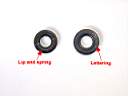 |
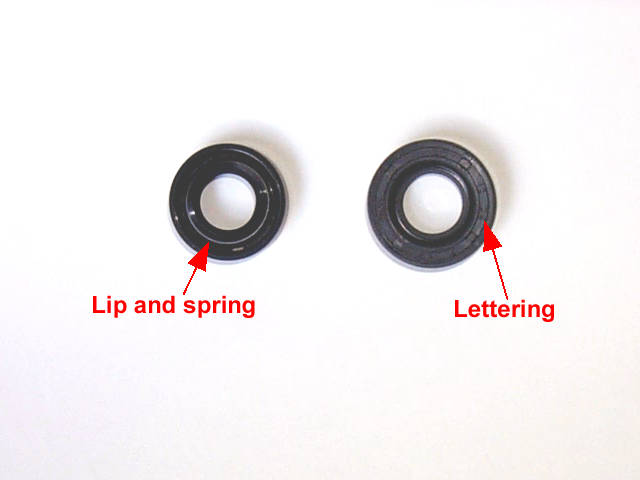
These are to two seals used inside the pump.
They are made of rubber with a metal spring inside. Both are made by
a company called Chicago Rawhide. The
larger (coolant side) is number CR-4715 (12x24x7) and the smaller (oil side) is
part number CR-4711 (12x22x7). You can buy these seals from Lotus or from any shop
that sells seals and bearings. Cost is only about $2US each,
so buy a couple of each in case you accidentally damage one while
inserting it. Note that the seals are inserted into the pump with
their flat sides facing each other. |
| 13 |
To help insert the new seals you
can use a hex socket of the same diameter as the seal. First, lubricate
the seal in a solution of 10% dish detergent. The seals are a very
tight fit and the solution will make them easier to insert. Place the
seal in the housing, and move it into place with the hex socket with
the aid of a bench vise. Be careful that the jaws of the jaws of
the vise do not mar the gasket surface of the pump. Also, make sure to
drive the seals all the way in. If they are not seated fully, they
will leak and you will have to repeat the process. |
| 14 |
Inspect the O-ring on the end of the pump shaft and make sure it is
in good condition. Replace if necessary. |
|
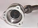
This is the front view of the pump. The shaft in the foreground is
spun by the auxiliary shaft from the engine. Note the O-ring is about
40mm from the end of the shaft. |
 |
| 15 |
Coat the pump shaft with motor oil and reinsert gently into pump
housing being careful not to damage the seals. Owners have
inadvertently damage the seals while dry "test-fitting" the
shaft so always lube the shaft first. |
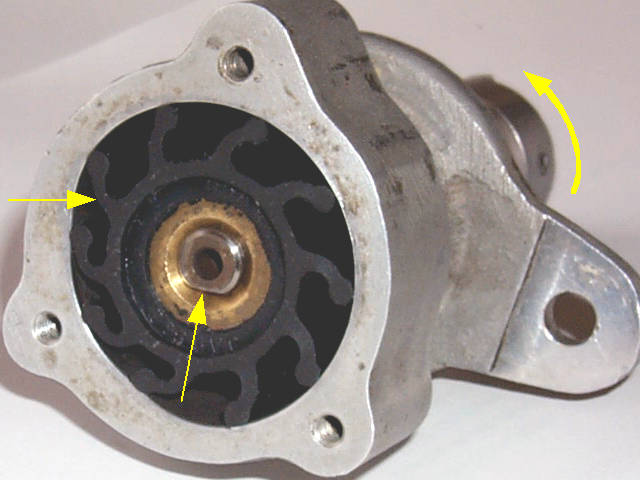
| 16 |
Coat the inside of the pump housing and the impeller with a healthy
dose of petroleum jelly. This will help prevent damage to the impeller
the first time the pump runs before the coolant has had a chance to
fully go through the system. Insert the impeller into the housing by
lining up the flat side on the shaft and impeller (see arrow in
picture below) and by carefully
bending the vanes in the direction of rotation. Note that, while the
impeller can be inserted with either side first, the vanes must bend
as shown in the picture or they will break off when pump tries to spin
them in the correct direction. |
|
 |
When assembling the pump, coat the inside of the
housing and the impeller with petroleum jelly to lubricate it. Make
sure to align the impeller center properly on the shaft. Also note the
direction of the blades on the impeller. They must match the ones in
this picture. The shaft should only be spun in the direction shown by
the arrow in the picture. |
| 17 |
Coat the mating surfaces of the pump housing and the end cover with
petroleum jelly and place a new paper gasket in between them
prior to joining both parts. The gasket is not symmetrical, so it can
only go in one way. Apply thread locking compound to the thread of the
three end cover screws and tighten them to 2.5Nm. |
| 18 |
Rotate the pump shaft to bring the tang back to the original
position you noted when you removed the pump, otherwise you will not
be able to reinsert the pump into the auxiliary shaft housing. Make
sure that you only rotate the shaft in the direction indicated
on the end cover of the pump or you might damage the vanes on the
impeller. |
| 19 |
Reattach the outlet hose to the outlet (bottom) spigot
on the pump and
tighten its hose clamp. Thread this hose back through its original
route back to the chargecooler. While holding the pump, attach the
inlet hose and tighten its clamp. |
| 20 |
Carefully maneuver the pump back into the auxiliary housing. If you
aligned the tang correctly, the pump should slide in with little or no
resistance. If not, do not force the pump in or attempt to use
the fixing screw to drive it in. This will most certainly cause damage the
pump housing. Instead pull the pump out, realign the shaft tang and try
again. Once it is in
place, hold it in place with its fixing screw, making sure not to
forget to replace the ignition wire routing clip. |
| 21 |
Reconnect all hoses and ignition wires, and replace the oil filter,
air filter, and air box. |
| 22 |
Refill the system with coolant. Do not attempt to run the
engine with the system dry or you will damage the impeller again. For
a procedure on how to refill the chargecooling system
click
here. |
|